The output transmission speed sensor location plays a crucial role in monitoring the transmission’s performance. Let’s delve into the specifics of where to find this essential component.
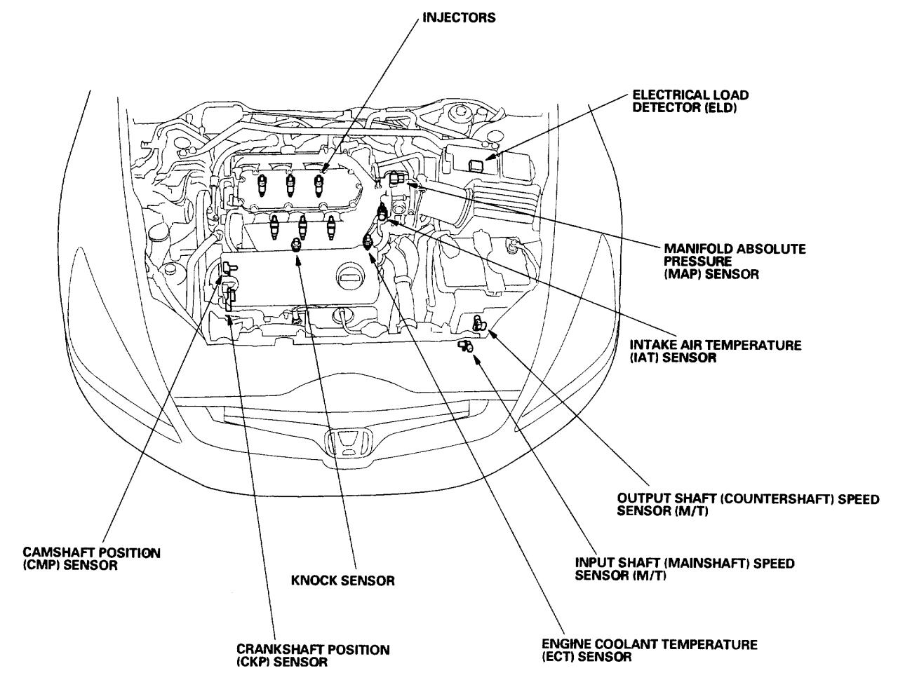
Typically, the sensor is mounted near the transmission’s output shaft, often close to the differential or driveshaft. Its proximity to these components allows it to accurately measure the rotational speed of the output shaft.
Location of Output Transmission Speed Sensor
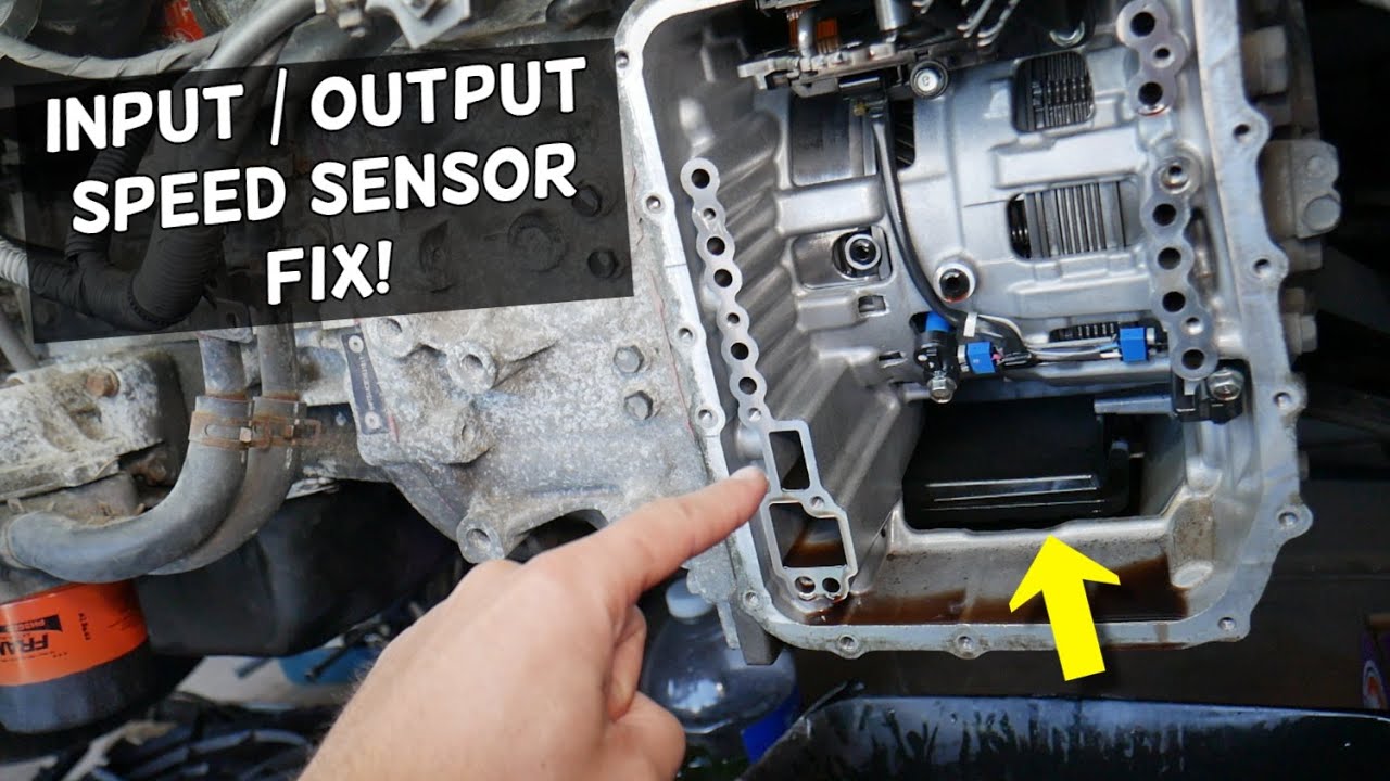
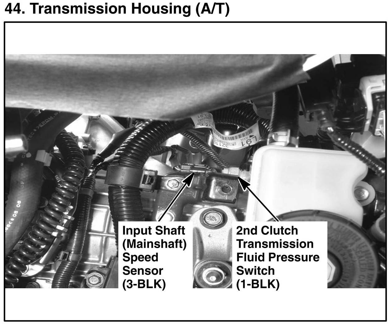
The output transmission speed sensor is typically located in the transmission case, near the output shaft or differential. It is usually mounted on the transmission case or on a bracket near the output shaft. The sensor is typically accessible for inspection and maintenance purposes, but the specific location and accessibility may vary depending on the make and model of the vehicle.
Mounting Location
The output transmission speed sensor is usually mounted on the transmission case or on a bracket near the output shaft. The specific mounting location may vary depending on the make and model of the vehicle. In some cases, the sensor may be mounted on the differential.
Accessibility
The output transmission speed sensor is typically accessible for inspection and maintenance purposes. However, the specific accessibility may vary depending on the make and model of the vehicle. In some cases, it may be necessary to remove other components, such as the transmission pan or the driveshaft, to access the sensor.
Purpose and Function of the Sensor
The output transmission speed sensor, also known as the output shaft speed sensor, plays a vital role in the proper functioning of a vehicle’s transmission system.
Function of the Sensor
The primary function of the output transmission speed sensor is to monitor and measure the rotational speed of the transmission’s output shaft. This information is crucial for the vehicle’s electronic control unit (ECU) to determine the appropriate gear ratio and shift timing.
The sensor measures the speed of the output shaft using a variety of techniques, including magnetic and optical methods. The sensor then transmits this data to the ECU, which uses it to control the transmission’s shifting patterns and adjust engine performance accordingly.
Role in Transmission Shifting and Engine Performance
The output transmission speed sensor plays a critical role in ensuring smooth and efficient transmission shifting. By providing accurate data on the output shaft speed, the ECU can determine the optimal time to shift gears, reducing wear and tear on the transmission components.
Furthermore, the sensor’s input helps the ECU optimize engine performance by adjusting fuel injection and ignition timing based on the transmission’s current gear ratio. This coordination between the transmission and engine results in improved fuel efficiency and overall vehicle performance.
Sensor Design and Construction
The design and construction of the output transmission speed sensor vary depending on the type of sensor used. Here are the details for different types of sensors:
Magnetic Sensors
- Magnetic sensors are inductive sensors that detect changes in magnetic fields. They consist of a coil of wire wrapped around a ferromagnetic core.
- When a ferrous object moves near the sensor, it creates a change in the magnetic field, which induces a voltage in the coil.
- The output voltage is proportional to the speed of the object.
Optical Sensors, Output transmission speed sensor location
- Optical sensors use light to detect the movement of an object.
- They consist of a light source, a photodetector, and a slotted disk or encoder wheel attached to the output shaft.
- As the disk rotates, it interrupts the light beam, which is detected by the photodetector.
- The frequency of the interrupted light pulses is proportional to the speed of the output shaft.
Hall Effect Sensors
- Hall effect sensors use the Hall effect to detect the presence of a magnetic field.
- They consist of a semiconductor material with a current flowing through it.
- When a magnetic field is applied perpendicular to the current flow, it creates a voltage difference across the material.
- The output voltage is proportional to the strength of the magnetic field, which is in turn proportional to the speed of the output shaft.
The materials used in the construction of the sensor include:
- Metals (such as iron, steel, or aluminum) for the core and housing
- Coils of wire for the inductive sensors
- Light sources (such as LEDs or lasers) and photodetectors for the optical sensors
- Semiconductor materials for the Hall effect sensors
Sensor Wiring and Electrical Connections

The output transmission speed sensor relies on electrical connections to function properly. Understanding the wiring and electrical connections is crucial for its accurate installation and operation.
Power Supply
The sensor requires a power supply to operate. This is typically provided by the vehicle’s electrical system, with the voltage varying depending on the specific sensor and vehicle model. The power supply wire is usually color-coded for easy identification.
Ground
A proper ground connection is essential for the sensor to function correctly. The ground wire provides a reference point for the sensor’s electrical circuit and ensures accurate signal transmission. The ground wire is typically black or brown in color.
Signal Output
The sensor’s output signal is transmitted through a dedicated signal output wire. This wire carries the electrical signal generated by the sensor, which represents the transmission speed. The signal output wire is usually shielded to minimize electrical interference.
Wiring Diagram
A wiring diagram or schematic can provide a clear visual representation of the sensor’s electrical connections. This diagram typically includes the power supply, ground, and signal output wires, as well as any additional connections required for the specific sensor.
Sensor Diagnostics and Troubleshooting: Output Transmission Speed Sensor Location

Diagnosing and troubleshooting a faulty output transmission speed sensor involves identifying common symptoms, performing step-by-step procedures, and utilizing diagnostic tools. By following these steps, technicians can effectively pinpoint sensor issues and restore optimal transmission performance.
Common Symptoms of a Faulty Sensor
A faulty output transmission speed sensor can manifest in various ways, including:
- Irregular shifting patterns
- Erratic speedometer readings
- Transmission slipping or shuddering
- Check engine light illumination
- Reduced fuel efficiency
Diagnostic Procedures
Diagnosing sensor issues involves a systematic approach:
-
-*Visual Inspection
Inspect the sensor for physical damage, corrosion, or loose connections.
-*Electrical Testing
Measure voltage and resistance at the sensor connector to ensure proper electrical connections.
-*Data Monitoring
Use a diagnostic scanner to monitor transmission speed sensor data and compare it to expected values.
-*Test Drive
Perform a test drive while monitoring sensor data to observe its behavior under different operating conditions.
Diagnostic Tools and Techniques
Various diagnostic tools and techniques can assist in troubleshooting sensor problems:
-
-*Diagnostic Scanners
Provide real-time data monitoring and fault code retrieval.
-*Multimeters
Measure voltage, resistance, and continuity.
-*Oscilloscopes
Display electrical signals, allowing for waveform analysis.
-*Transmission Speed Simulators
Emulate sensor signals to test sensor response.
Closure

Understanding the output transmission speed sensor location is essential for proper maintenance and troubleshooting. By knowing its whereabouts, you can quickly diagnose any issues and ensure optimal transmission performance.
Essential FAQs
Where is the output transmission speed sensor usually located?
Near the transmission’s output shaft, often close to the differential or driveshaft.
What is the purpose of the output transmission speed sensor?
To measure and transmit data on the output shaft speed of the transmission.
Why is the output transmission speed sensor important?
It plays a vital role in controlling transmission shifting and engine performance.